Process
Technical Insights
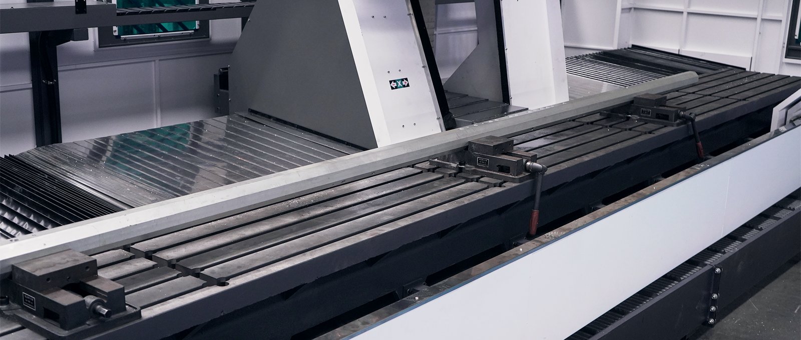
Holes out of position, burrs at hole edges, damaged threads — the usual reaction is to suspect machine accuracy first, then adjust parameters, then change tools, and after a full circle the problem is still there. In reality most defects follow a fixed troubleshooting order: start with the element closest to the workpiece and work outward, layer by layer.
Step 1: workholding and locating (where most problems start)
- Is clamping force sufficient — air pressure at specification, no leaks, clamp pads free of chips and oil?
- Is the locating datum the same as the drawing datum?
- Is there a chip or burr on the locating face? One chip can shift the hole position of an entire batch
- Are long profiles supported in the middle? Unsupported spans deflect and spring back under cutting force
- After turning the part or the table, has the datum been re-established?
Step 2: tooling
- Is the cutting edge worn or chipped? A small chip is the main source of heavy burrs
- Are the toolholder taper and spindle taper clean? A trapped chip causes runout — oversized holes and chatter marks
- Is tool overhang too long? Longer tools mean less rigidity, more chatter and deflection
- Is the drill still within its life? Hole size drifts as the number of holes accumulates
- Does the tap drill diameter match? Oversized causes thread stripping; undersized breaks taps
Step 3: cutting parameters and chip evacuation
- Do speed and feed match? Feed too high with speed too low is a classic source of burrs and poor finish
- Prefer climb milling: cutting force presses downward and reduces edge burrs
- Use peck drilling with retract for deep holes so chips do not score the wall
- Is cooling or air blast adequate? Chip welding and rough hole walls usually point to insufficient cooling
- Are chips cleared promptly? Accumulated chips scratch finished surfaces
Step 4: program and machine condition
- Is tool length compensation up to date after a tool change or regrind? Forgetting it shifts all dimensions
- Does the work coordinate origin match the current fixture — especially after a changeover?
- In multi-face or rotary machining, is the coordinate transformation correct?
- Guideway lubrication and ballscrew condition: backlash and stick-slip show up directly as unstable dimensions
- Spindle thermal growth: dimensions drift during long runs, so warm up and spot-check periodically
Quick reference for common symptoms
- All holes shifted → check datum and clamping first, then work coordinate origin
- Holes oversized → check tool runout and taper cleanliness, then compensation
- Burrs at hole edge → check edge condition and feed, then consider a chamfering operation
- Thread stripping → check tap drill size, then tapping speed and lubrication
- Chatter marks → check clamping rigidity and mid-span support, then shorten tool overhang
- Dimensions drifting within a batch → check tool wear, then spindle thermal growth
Last step: write down what you found
Troubleshooting order and corrective actions
| Symptom | Usual causes | Check in this order | Corrective action |
|---|---|---|---|
| Hole position offset | Fixture not seated, chips on the datum, thermal growth, screw backlash | 1) Re-check fixture and datum → 2) verify work offset and tool compensation → 3) measure repeatability | Clean the datum, add clamping points, let the first part stabilise thermally, check and compensate backlash |
| Burrs at hole exit | Worn cutting edge, feed per tooth too high, spindle speed too low, poor chip evacuation | 1) Inspect the cutting edge → 2) check feed/speed matching → 3) observe chip evacuation and cooling | Change or regrind the tool, reduce feed per tooth, raise spindle speed, add coolant or air blast |
| Torn threads or broken taps | Wrong pilot hole, spindle not concentric with the hole, feed not synchronised to pitch | 1) Measure the pilot hole → 2) confirm rigid tapping is enabled → 3) check tap wear | Correct the pilot hole, enable rigid tapping (synchronised G84), replace the tap, reduce spindle speed |
| Slot width out of tolerance | Tool run-out, wrong tool compensation, degraded positioning accuracy | 1) Measure tool run-out → 2) verify compensation → 3) check the machine with a ballbar or laser interferometer | Replace holder or collet, correct compensation, schedule accuracy calibration and screw preload adjustment |
| Poor surface finish | Speed/feed mismatch, excessive tool overhang, insufficient rigidity | 1) Read the chatter pattern → 2) check tool overhang → 3) trial-cut with adjusted parameters | Shorten overhang, raise speed or reduce feed per tooth, reduce radial depth of cut if needed |
Frequently asked questions
- When hole positions shift uniformly, why check workholding before suspecting machine accuracy?
- Machine accuracy degrades gradually and rarely shows up as a sudden uniform shift. A sudden shift almost always means the datum moved: chips on the locating face, insufficient clamping force letting the part creep, or a work offset not updated after a changeover. Working through the sequence clamping - tooling - cutting parameters - program and machine resolves most cases at the first step, without touching the machine.
- Is a stripped thread always caused by a poor-quality tap?
- No. The usual causes, in order: tap drill too small so the load is excessive, tapping feed and speed out of sync, tap not concentric with the pilot hole, or insufficient lubrication causing heat build-up. Tap wear and mistaken tap selection come later in the list. Check the pilot hole size and the sync relationship first, then consider changing the tap.
- Dimensions change suddenly after a tool change or regrind - where should I look first?
- Check that the tool length offset matches the new tool. After a change, regrind or re-clamping, the actual length has changed, and if the offset is not updated the whole feature shifts. Next, check whether chips are trapped between the spindle taper and the toolholder, which causes runout, oversized holes and chatter marks. Together these account for the great majority of such cases.
- Heavy burrs at the hole exit on aluminium profiles, and sharpening the drill did not help. What next?
- First check whether the feed is too high for the speed: that is the most common burr source, and reducing feed often works better than regrinding. Next confirm you are climb milling, where the cutting force acts downwards and markedly reduces edge rollover. Support the exit side too, since a backing plate prevents breakout on thin walls. Also inspect the cutting edges under magnification; a tiny chip produces large flake burrs.
After each defect, log the symptom, the real cause and the fix. Once you have a few dozen entries you will see that only a handful of causes recur — and new operators can work from the log. That is worth far more than any one-off machine adjustment.