Process
Technical Insights
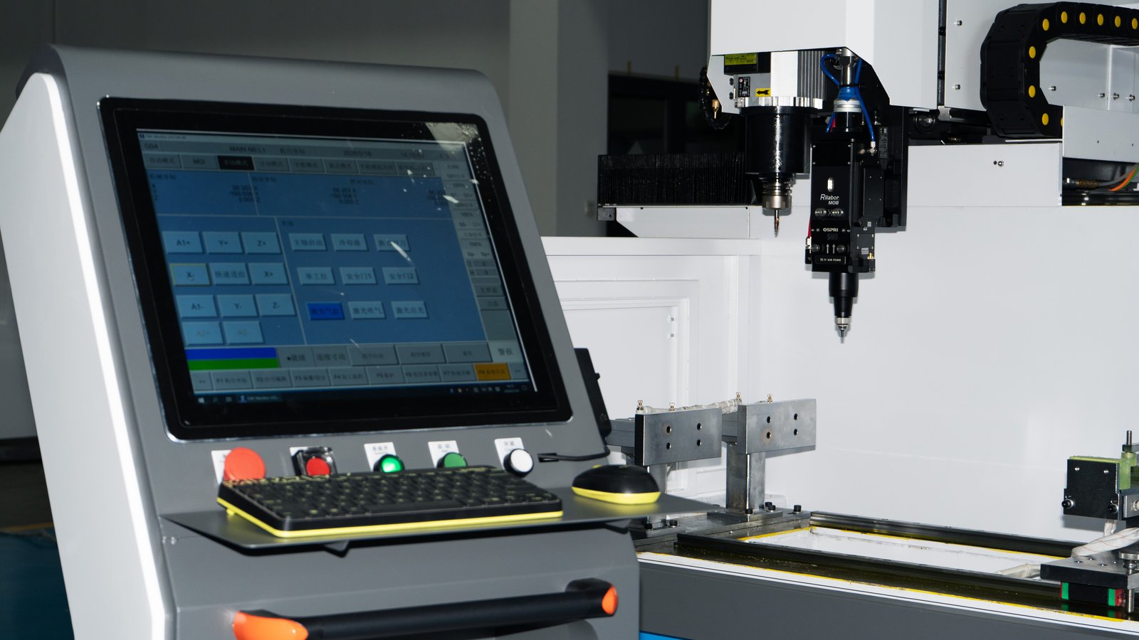
Machining solar frame and mounting profiles looks unremarkable: an aluminium extrusion, a few holes, a couple of slots, cut to length. But the real difficulty is never whether you can make one part — it is whether part number 8,000 matches part number one. A single order often runs to thousands of identical pieces, and a length or hole-position deviation does not stay contained. It propagates down the line into assembly gaps, mismatched corner keys, and rework on site. In this industry the measure of a machine is not the accuracy it achieves once, but the consistency it holds over a long run.
1. Set the datum first: everything follows from cut length
Hole positions on frame profiles are almost always dimensioned from the end of the extrusion. That makes the length produced by the saw the coordinate origin for every downstream hole. If cut length drifts by ±0.3mm, no amount of drilling precision will hold hole-to-end distance. Plan sawing and drilling-milling as one system, not two independent operations.
- Establish the length tolerance your saw can actually hold, then derive the compensation allowance the drilling cell needs
- Use a single datum: reference every hole pattern to the same end face or the same locating pin
- If the part needs end milling before drilling, confirm whether both can happen in one setup to avoid a second clamping
2. Hole layout drives cycle time, not hole count
The common estimating mistake is counting how many holes a profile has. What actually sets cycle time is how those holes are distributed: 30 holes clustered in one section and 30 holes spread over six metres can differ by a factor of two, because the table has to travel the full length.
- Count hole diameters: more sizes means more tool changes and more non-cutting time
- Separate through holes, counterbores and threaded holes: the last two need extra operations and must be costed separately
- For long workpieces look at rapid traverse rate, not just maximum cutting speed
- Cycle time per bar ≈ positioning travel + sum of hole machining times + tool changes × change time + load/unload
3. Tool magazine: inline or carousel
Frame profiles typically use four to eight hole diameters — few sizes, but frequent changes. In that range the trade-off is clear: an inline magazine is mechanically simple, has a short change path and fewer failure points, and suits a stable product with a fixed tool logic; a carousel holds more tools and suits complex, varied work. If the product structure is stable long term, the inline layout usually wins on both maintenance cost and cycle time.
4. When an inline fibre laser is worth it
Several operations on frame profiles are either slow with conventional tools or need a separate station: grounding marks, QR codes, odd-shaped holes in thin walls, local oxide removal. These are exactly what a fibre laser does well. Integrating the laser head into the machining centre is not about adding a feature — it is about eliminating one extra clamping and one transfer between operations.
- First work out how many extra transfers per year these operations currently cost you, and how much labour
- Confirm the laser power covers your material thickness and cycle-time target
- Budget for guarding and extraction — this is the item most often underestimated
5. Three levers for batch consistency
Long-term consistency comes not from the accuracy figure in the brochure but from three daily disciplines.
- Tool life management: force tool change by part count or cutting hours, do not wait for a broken edge
- Clean locating surfaces: aluminium chips are the most common cause of hole drift, clear them every shift
- First-piece and sampling records: log the drift trend and catch it before it goes out of tolerance, not after scrap
Cycle-time components for solar frame machining and how to optimise each
| Cycle-time component | Main drivers | Practical optimisation |
|---|---|---|
| Cutting time | Hole diameter and depth, feed and speed match | Match tool geometry to the alloy instead of running permanently conservative parameters |
| Tool-change time | The number of different hole sizes sets the change count | Frames usually need 4–8 sizes; prefer a short-path magazine such as the WGTA-4500 disc type with 16 pockets and 2 s change |
| Axis travel time | How the holes are distributed along the length, not the total count | Sequence holes by proximity to cut idle travel when they cluster |
| Loading and locating | Cut-to-length consistency is the datum for every hole | Treat sawing and machining as one system; clean datum faces every shift |
| Marking and coding | Earthing symbols, QR codes, local oxide removal | Integrate a 3 kW fibre laser (WGT-3000G) and eliminate one extra setup |
| Tool-life management | Whether a mandatory tool-change policy is in place | Replace tools by part count or cutting hours rather than waiting for chipping |
FAQ
- What tolerance standard applies to hole positions on frame profiles?
- Hole-position tolerance is normally set by the module assembly requirement, commonly within ±0.2mm on hole-to-hole distance. Always work from the drawing supplied by the module maker rather than a generic machining tolerance.
- How do I choose table stroke for profiles over six metres?
- Size it from the longest workpiece plus clamping allowance at both ends. If you regularly machine at full stroke, watch for accuracy drift from guideway wear and specify a linear scale for closed-loop control.
- Inline or carousel magazine — which suits frame work better?
- Frame profiles use a relatively fixed set of diameters, often four to eight, so an inline magazine with its short change path and simple maintenance usually fits best. Consider a larger carousel only if the product range is wide and the process complex.
If you are planning a line for solar frame or mounting profiles, send us your section drawing, hole list and cycle-time target, and we will come back with a matching machine configuration and cycle-time calculation.